Harvest Light Part II
31 July, 2016
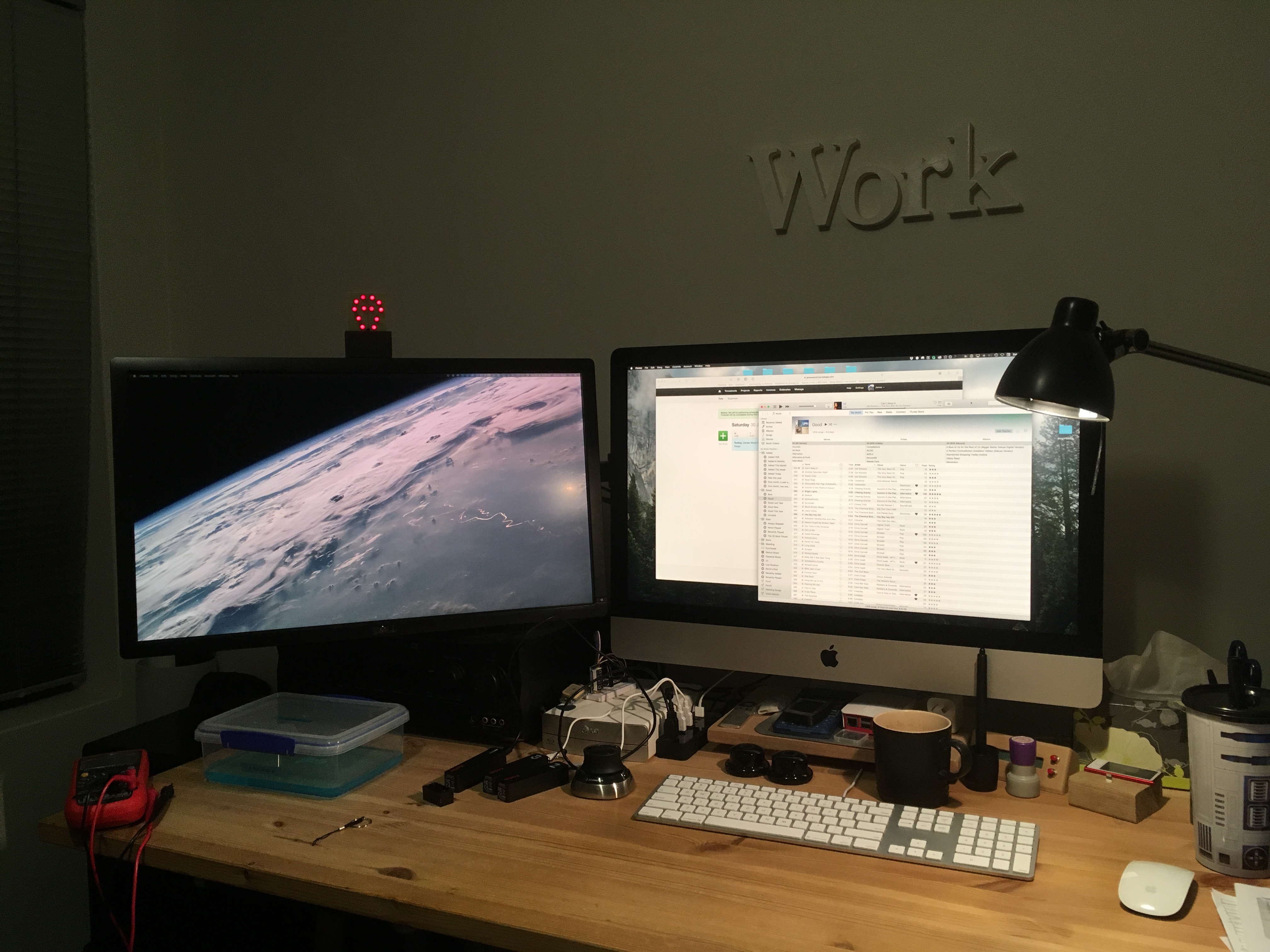
I built a thing to help me track my billable work. It was a bit rough, so I decided to improve it.
Simpler Hardware
The Node MCU I used for the first revision was overkill. It has a whole load of input/output pins that I didn’t need. All the hardware this project really needs is wifi and a single I/O pin. The ESP-01 is a better fit - it has two output pins (I don’t think there’s anything with less than that), and it costs under five bucks. They can be tricky to work with, but they’re not too bad once you get the hang of them.
Instead of having the microcontroller and lights on separate prototyping PCBs, I decided to design and make a custom PCB. My technique is… wonky. But I’m getting better!
Custom PCB
Design
I used Fritzing to design the board. The first step is to draw the schematic, then switch to PCB mode and lay out all the components. Then the tracks are routed between them. Then all the tracks are deleted, the components repositioned and the tracks re-routed three hundred times because there’s no right answer and there’s always a better way. I like what I ended up with… but I made a few rookie errors.
Transfer
Once the design is finished, it needs to be transferred onto a blank PCB. A blank PCB is a thin piece of fibreglass with a copper coating on (in this case) one side. The design is masked off, and then the unmasked copper is etched away with a chemical.
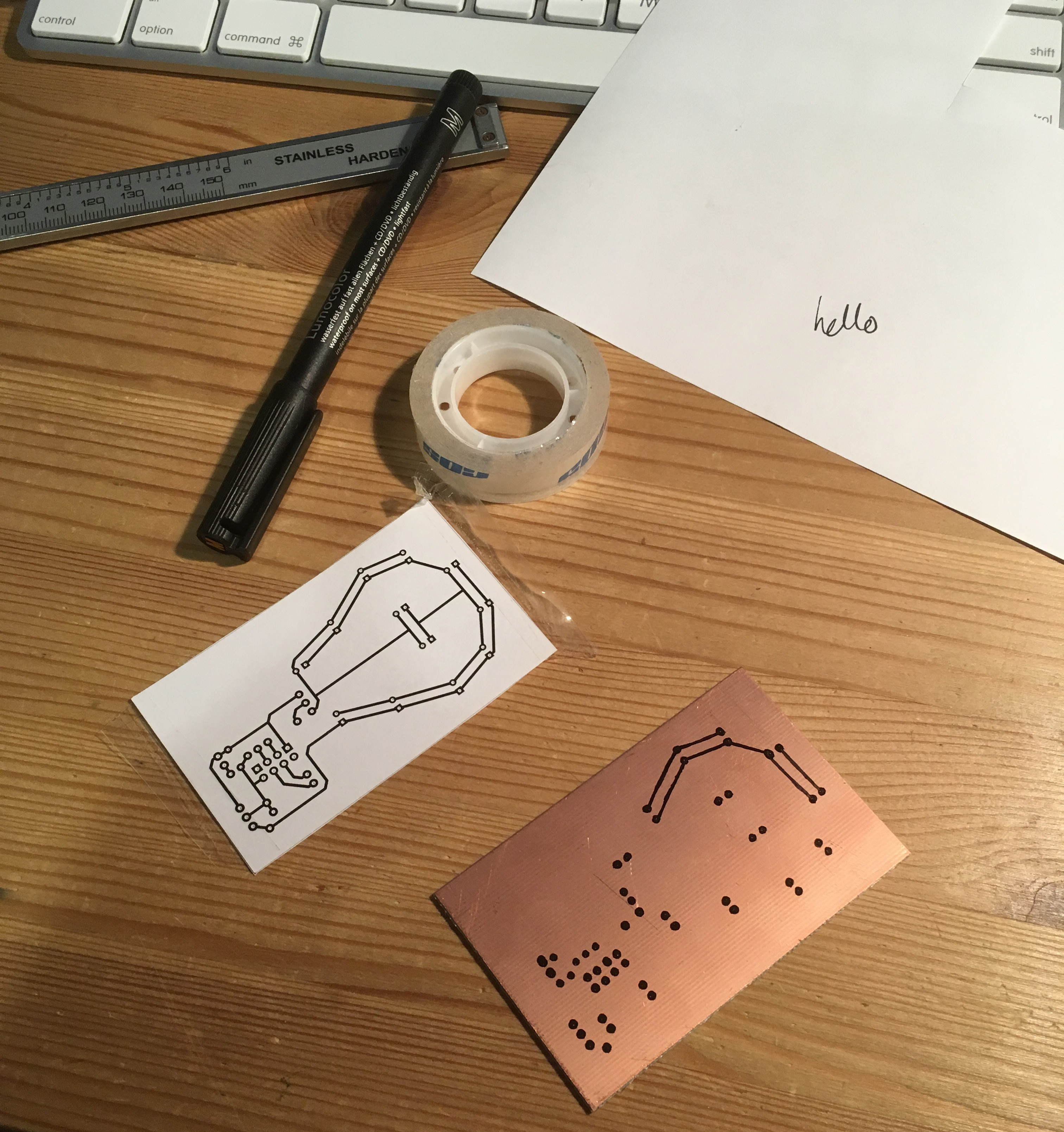
I printed the design and taped it to the blank board, then used a file to poke the paper wherever a hole would be drilled. After that I removed the paper and joined the dots with an etchant-resistant pen. (I think I probably should have washed the board first, because the pen turned out not to be as resistant as it should have been, and some tracks were… not great). In a tradition that extends back to my earliest days of board-making, I forgot to draw one trace and had to add a wire later on. It’s a style.
Etch
The masked board went into some gently warmed etchant. I used Sodium Persulphate and it took hours. I’m not sure why. I’m using cheap PCBs and maybe the copper isn’t super pure? Or maybe my etchant is getting old. Either way, the long etch time meant that some tracks were etched completely away before the rest of the copper was gone. This might have been partly due to forgetting to wash the board before masking it. Either way, next time I’m going to try a mixture of hydrochloric acid and peroxide, which is apparently very effective.

After etching, I rinsed and dried the board ready for drilling.
Drill
I used a tiny tungsten carbide bit in a giant drill press. It worked but it was tricky to align the bit exactly with the pads. Next time I’ll use the bit in my dremel-like-tool, to get slightly more control over where the holes are. For most components it didn’t matter too much, but the 8-pin microcontroller wouldn’t fit and I had to re-drill one of its holes.
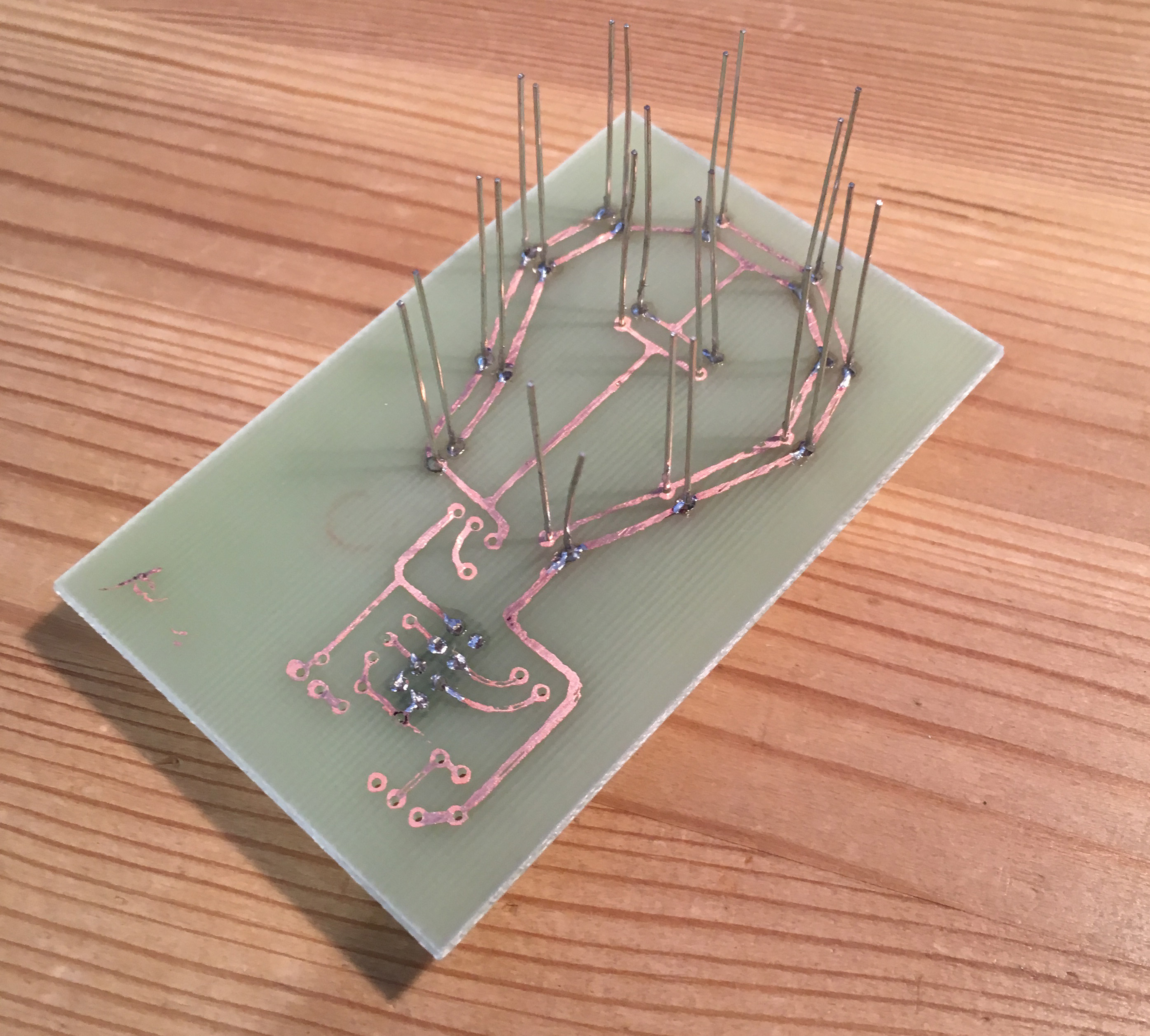
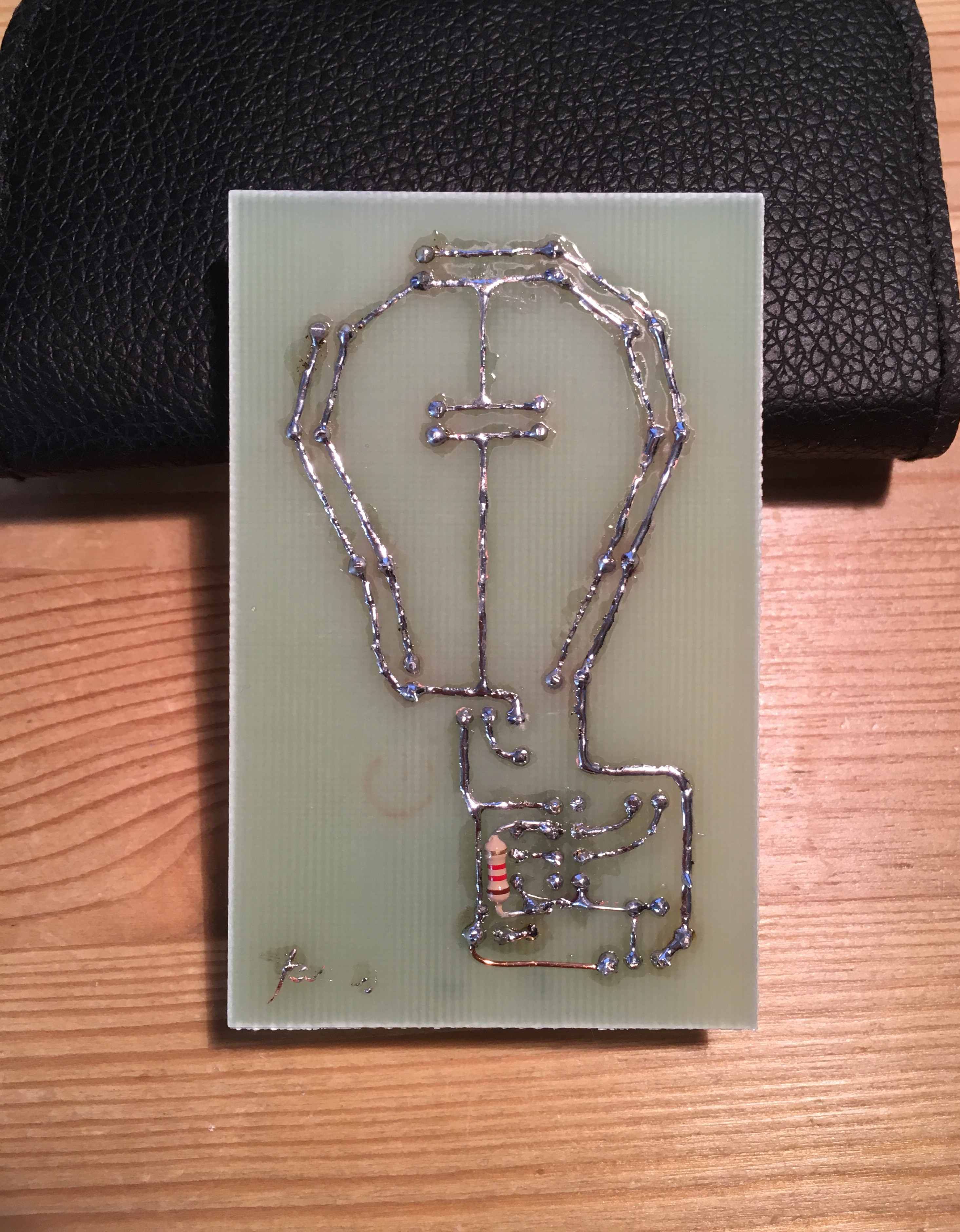
Assemble
Put the bits in the thing! Solder all the pads! I also ran some solder over the thinner PCB tracks to protect them from corrosion and to make better electrical contact. Then I ran some over all the other tracks anyway. So now the whole thing gleams!
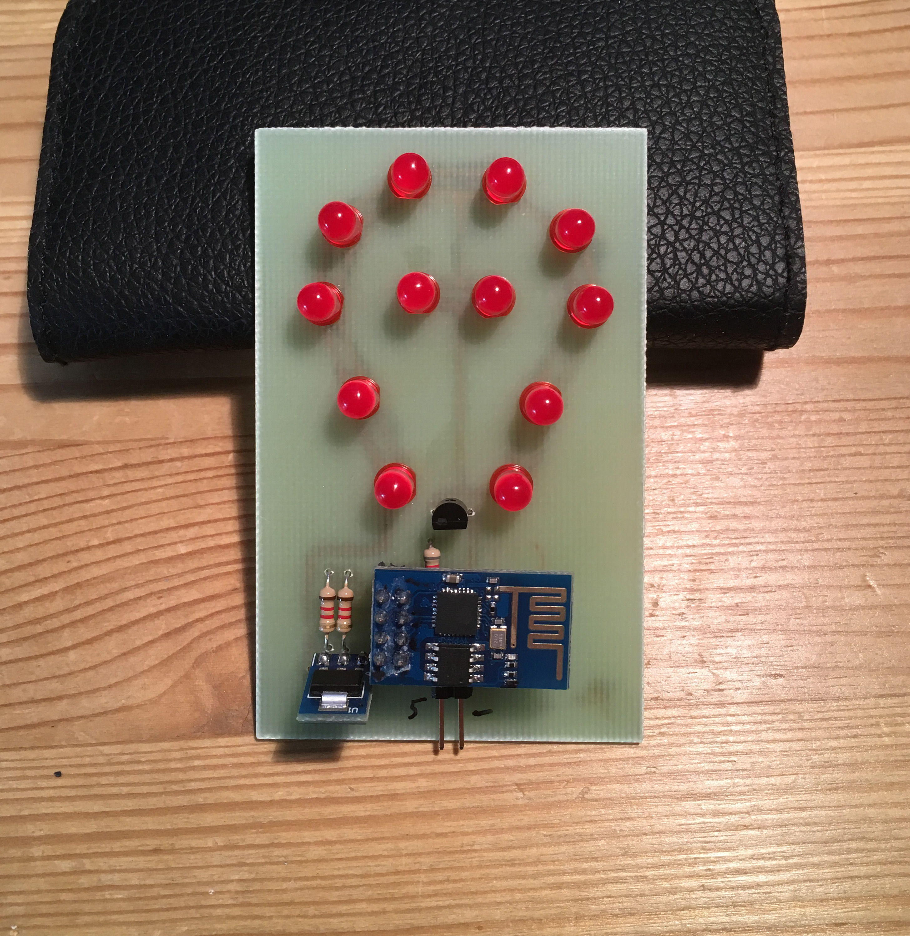
Testing Time
Switch on… and crash. All the LEDs were dimly lit. This shouldn’t have been possible - the circuit pretty much allows them to be on or off, not dimly lit. Turns out that the ESP-01 has to have both of its output pins pulled high (connected to the positive supply voltage) when it boots, to tell it not to go into firmware upgrade mode. My circuit didn’t do that, because I am using one of the pins to drive the LEDs. I added a pullup resistor to that pin, which fixed the problem and the board sprang to life.
Custom Case
If this thing is going to get out of the way and do its job, it needs to be a permanent fixture.
Design
I used Autodesk Fusion to design a really simple push-fit case. I decided to leave the top half of the circuit board exposed. Making room for a power connector would have meant a larger case, so I drilled a hole in the PCB and mounted the barrel connector there. Then I realised the wifi module would no longer fit, so I drilled another hole and tried again. Success! The thing will sit on top of my second monitor and get power from one of the monitor’s USB ports.
Assembly
The PCB drops into the front half of the printed case, and then the back panel pushes in. It holds the PCB pretty tightly and is a fairly snug fit. The case can be reopened with a bit of tugging. Push fit works well for 3d printed cases because the layers of plastic that make up the print grip each other and stay snug. (I usually leave a 0.1mm gap between the touching surfaces, and bevel the corners of any inside pieces.)
Finished!
I’m pretty happy with this.